The reading room
How to read your first engineering drawing
A mounting plate, two holes and a deceptively simple question. Could someone else make the part you drew?
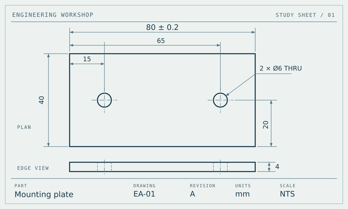
Imagine handing a classmate a sketch of a mounting plate for a small motor. You know how it should fit because you drew it. Your classmate sees a rectangle and two circles. Which tools should they pick up? How far apart should they drill the holes? An engineering drawing lets the two of you answer those questions without having to stand at the same bench. Try reading the practice sheet above before reaching for a ruler.
Start in the corner
Look at the title block. The part is a mounting plate, the drawing number is EA-01 and the revision is A. If a second sheet has the same number but a different revision, establish which version the job requires before anyone starts cutting. Check the units too. On this sheet the dimensions are in millimetres. A screenshot can shrink to fit a phone or expand to fill a projector. The printed dimension still describes the same piece of metal.
Find the solid behind the lines
The plan shows the plate looking down on its broad face. The two circles are holes. Now follow one circle down to the narrow edge view. The dashed lines mark the sides of the hole that the surrounding metal hides from this direction. The callout beside the plan confirms that both holes pass all the way through. The edge view adds something the plan cannot tell you on its own. The plate is four millimetres thick.
Locate a centre before sizing the hole
Each hole has a diameter of six millimetres. That describes its size. Its centre needs a position as well. Start from the left edge. The first centre lies fifteen millimetres in and the second lies sixty-five millimetres in. Both are twenty millimetres above the bottom edge. Their centres are therefore fifty millimetres apart. If you measured the gap between the nearest edges of the holes instead, you would get forty-four millimetres. Write down which distance you mean. A useful check is to measure back from the right edge. The second centre should sit fifteen millimetres inside it, just like its partner opposite.
Read the limits as well as the target
The overall length is marked 80 ± 0.2. An inspector checking that dimension can accept a length from 79.8 to 80.2 millimetres inclusive. A reading of 80.3 falls outside that interval. Passing this check says nothing yet about the holes. A plate could be precisely eighty millimetres long with both holes shifted to one side. In a workshop notebook, give each feature its own line and record what you actually measured beside the requirement.
Try the handover test
Cover the drawing and tell a partner how to mark the two centres on a paper rectangle. Ask them to read the positions back to you, including their starting edges. Then uncover the drawing and compare. If the numbers agree but the marks are in different places, you have discovered why engineers specify a reference edge. For a final check, turn the paper over. Decide which details survive that change of view and which need a second view to explain them. That is a good question to take into your next design review.
Sources and further reading
- MIT OpenCourseWare • Engineering Drawing and Sketching · Checked 2026-11-08
- WJEC • Understanding engineering drawings · Checked 2026-11-08